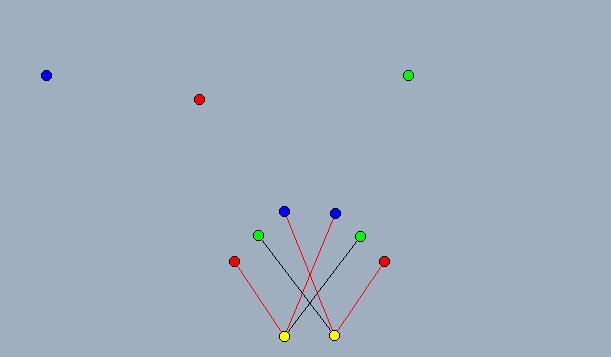
The proceeding illustration shows the neural network. The input
nodes (sensors)
are red, green, and blue. The output nodes (motor control) are
yellow.
Red lines indicate excitory connections, and black lines indicate inhibitory
connections.
The points which are not connected to anything represent stimuli.
In terms of the game,
blue corresponds to the player, green to other robots, and red to missiles.
The red sensors are receptive to the red stimulus, et cetera.
Each stimulus has an intensity value associated with it. To calculate
the activity of a given input node, the intensity of the stimulus
is divided by the Euclidean distance squared between the stimulus and
the receptive sensor.
The signals from the input layer are propagated to the output layer
via the weighted connections.
If we were to ignore the red and green stimuli in the picture, and
calculate the activity of the motor
control nodes, we would find the activity of the left motor control
node to be less than the activity
of the right motor control node, and the robot would subsequently turn
to the left.
The next picture illustrates the method for updating the robot's position.
The dark yellow points
represent the locations of the motors. The yellow polygon represents
the robot. The red lines
represent the velocity vectors of the motors. The green line
is defined by the heads of the velocity
vectors of the motors. The yellow line is defined by the locations
of the motors. To compute the robots next position, take the point
of intersection of the green and yellow lines, and take the angle
formed at that intersection. Then rotate the robot about that
point a number of degrees equal to the
angle. You can change the direction and magnitude of the velocity
vectors by dragging the red points
to see how the point of intersection and the angle change. Please
note that while this construction
allows you to change the directions of the velocity vectors relative
to each other, that this does
not happen in the game.
Created with Cinderella