Working for Joe O'Rourke of the Computer Science Department
Summary of Research:
This summer I used computer software to design three-dimensional models of all five Platonic solids in Leonardo da Vinci’s solid edge form. I used the computer to capture renderings and learned to operate the three-dimensional printer (also known as a rapid prototyping machine) to create physical models of all five shapes. I did most of my work in Alias Studio 12, but towards the end of the summer I also used Mathematica to construct the models in a different way.
The five Platonic solids are the cube, the dodecahedron, the icosahedron, the octahedron, and the tetrahedron. The different shapes provided different challenges. The dodecahedron has twelve faces, each of which is a regular pentagon. As it was my first shape, much of the difficulty was in deciding how to build the shape. I ended up rotating five rectangular prisms and fitting them together into a pentagonal face. I then duplicated this shape and rotated the copy so that the faces fit at the correct dihedral angle. Next came the cube, which was without complications. The tetrahedron (composed of four faces, each of which is an equilateral triangle) proved more challenging. The angles of the tetrahedron are all acute, which means that the faces stick out through each other if they are not beveled correctly. It was a long process of trial and error, but eventually it worked out. The icosahedron was complicated because of the sheer number of rotations involved. It has twenty faces (again equilateral triangles), each of which must meet at an angle of approximately 138.19°. The rotations become more difficult to compute when the faces are further removed from the original face. Like the tetrahedron, the octahedron had to be beveled to keep edges from sticking out through each other.

Models of Platonic Solids, from left to right: cube, octahedron, icosahedron, and tetraehdron. All were created using Alias Studio 12.
One of the reasons we built the Platonic solids was to build a replica of Kepler’s model of the solar system. This was Diana’s project, but she used my models of the Platonic solids. In order to get the shapes thin enough for the punch bowl, Professor O’Rourke and I worked to create the Platonic solids using Mathematica. With these model designs it is possible to change the thickness of the edges by changing only a single variable in one equation instead of starting over from the beginning (as you would have to do in Alias).


Left: A computerized rendering of the dodecahedron. Center: Image of tetrahedron as designed with Mathematica. Right: Kepler’s model of the solar system.
After starting the 3D printer on five sets of Borromean Rings this morning we went to have our tutorial on using dreamweaver so that we will be able to post a web journal about our research. We started on Monday May 16, and it's been a fun and exciting week. Samri and I started out working on protein folding, trying to find (or find that we couldn't find) a locked 45 degree unit chain. We found a chain that may be locked, but since it was unclear where we should go next with the protein folding project and since there was so much to do on the work with the 3D printer, Joe decided that it would be better if we switched to working with the printer.
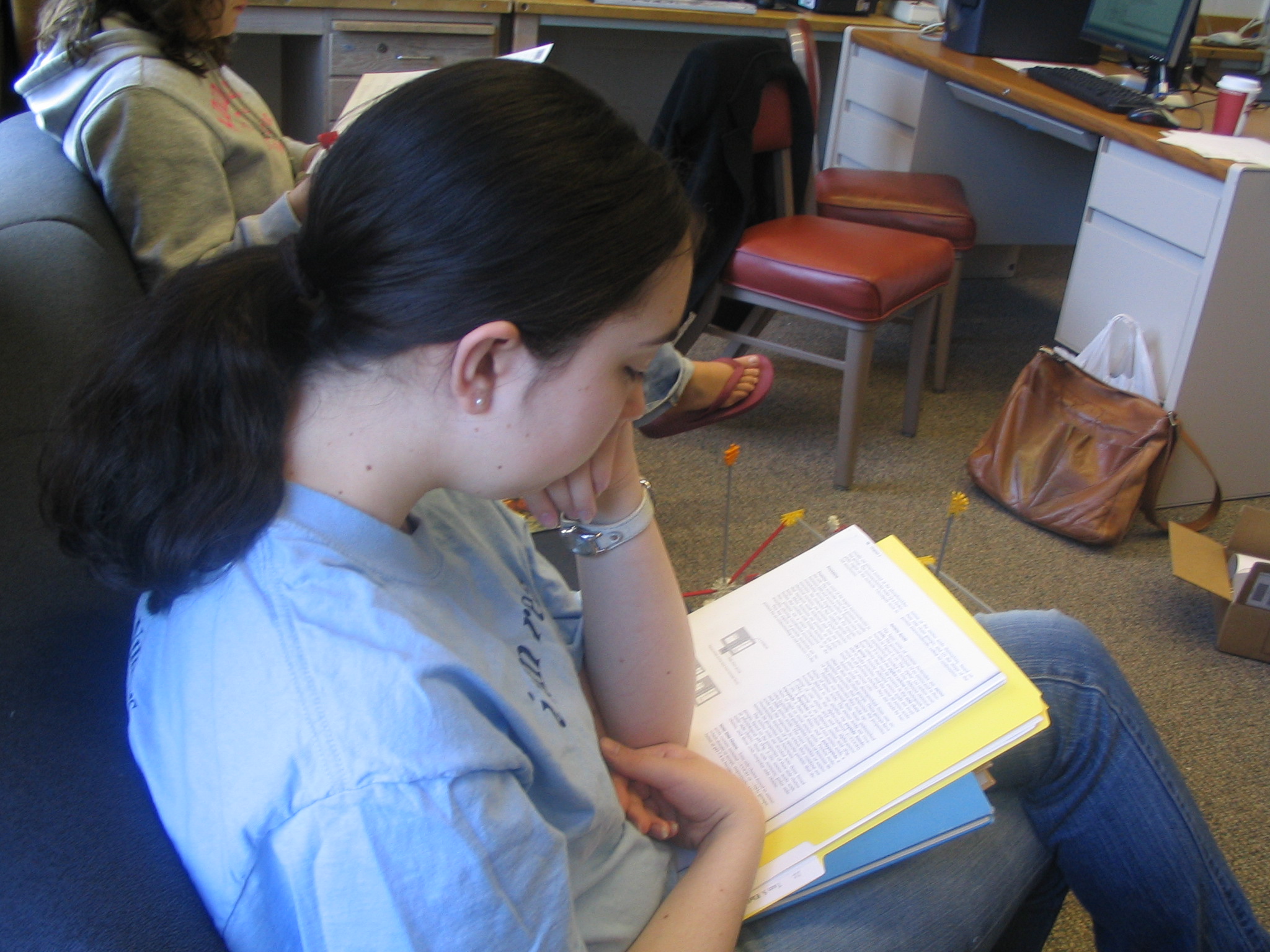
Left: I read an article on basic protein structure; Right: Our 45 degree unit chain which may or may not be locked.
We've been learning how to use Alias Studio 12. The simplest (and thus first) thing we did was learn how to create and transform basic solids: spheres, toruses, cubes, cones, and cylinders. Drawing curves (both in space and on surfaces) was also fairly simple. On Thursday I got to the point where I could make skins and even bind them together into objects (NURBs or Non-Uniform Rations B-splines in Alias terminology). The trick to connecting a large group (I did it with as many as thirty yesterday..) of skins so that Alias treats it as one object or surface (i.e. when you click on any part the whole object is selected, when you move any part the whole object is moved, etc.) is to convert the object to mesh and then use the merge mesh command to make it into one piece. You can also sew surfaces together, but I found this to be much more finicky (not to mention frustrating!). There is of course more than one way to combine surfaces (although many work only for objects created in certain ways), and I'm sure there are quite a few more that I don't know. But the trick of changing objects to mesh is very fast; it takes less than five minutes even if you don't know what you're doing. Our project for the week was to create different sets of Borromean Rings (made with different shapes). A set of Borromean Rings is a set of three interlocking noncircular rings (it has been proved that circular Borromean Rings cannot exist) interlocked so that any two are not interlocked while the shape as a whole is locked (i.e. the rings cannot be separated).
Left: A set of elliptical Borromean Rings that I created using Alias Studio 12. I created the ring shape by taking a torus and stretching it out along one axis. Right: A set of "peanut shaped" Borromean Rings (shape inspired by a paper by Jason Cantarella). I designed the ring shape (on Alius) by taking a torus, sawing off an end, and duplicating and then rotating the shape. I converted the torus to mesh (which is why it is so angular; I didn't put in enough triangles to make it really smooth looking) and used the merge mesh function to make it into one object (this is pretty much essential since I needed to rotate the duplicates of the rings).
I spent much of today working on Borromean rings, focusing on Cantarella's peanut shape. The goal was to construct a tighter model for the peanut shaped Borromean rings, but I realized this morning that I had been constructing the curve in a way completely different from what Cantarella had done. As his specific design has applications to knot theory, Joe decided that I should figure out how to create the smoother peanut shape. We had been cutting two tori off at the same place and gluing them together (as shown in the model above on the right), while Cantarella used a smooth shape constructed from arc segments of four circles of the same radius.
Note: I later realized that this diagram is in fact incorrect. See Tuesday, May 24 for the corrected diagram and explanation.
The new set of rings is much smoother, partially because they are not made from two pieces joined. To construct them on Alias I used the arc drawing tools to get the portions of each circle that I needed (as shown above). I did this by finding points on the circles and using them to define the four arcs that make up the backbone of the peanut shape. I then used the attach function on the right hand edit menu to join the four arcs into one piece (they were already connected because I had given the endpoints of the arcs to be the points of intersection between the circles and so using the attach function did not distort the shape at all. From there I saved my backbone shape and did several different versions of the peanut rings (with different ring thick nesses) by drawing a circle orthogonal to the peanut backbone and using the extrude function to get the three dimensional peanut shape. The different sets of rings are shown below.
Left: The first set of Borromean rings that I created using this method. This set is the loosest. Each ring has a radius of 30 mm. Right: I made this set after creating a set where the thickness of the rings reaches its limit (50 mm radius on this scale). At this size the rings virtually touch, which is not practical for model building. We decided to scale back the radius to allow for some movement. In this set the rings are 42 mm thick.
Tuesday May 24, 2005
This morning Joe and I discovered (to my great frustration), that my construction of the Cantarella peanut shape was still wrong. I had assumed that the vertical circles in the diagram were tangent to each other, but it turns out that they overlap slightly. A corrected diagram is shown below:
Because the circles are not tangent, the length AJ is not equal to AG, AD, DJ, and GJ (the sides of the rhombus, each of which are exactly equal to the diameter of each of the circles) as I had thought. Instead AJ = EF. I used the Pythagorean Theorem to solve for the distance from the origin to A, E, F, and J. It turned out to be approximately 82.29% of the radius. The distance from the origin to G and D is the distance from the origin to F plus the radius, or more simply 182.29% of the radius.
Luckily, I had saved my original circles in Alias, so it only took me the rest of the morning to recreate the Borromean rings with the corrected design. It took me all day to do it the first time, so it was at least quite a bit faster. The new shapes fit more tightly on the outer parts of the rings, which is helpful for applications to knot theory. My newest rings are shown below:
The set on the right is slightly thicker than the set on the left, as you can see. These rings are less elongated than the ones I built yesterday, as you can see by comparing them to the ones above. This allows them to fit more tightly with each other.
Wednesday May 25, 2005
We spent most of the morning preparing and starting the printer. Somehow it always takes us at least three tries to get the right amount of powder into the feed bin; we always feel like we've put in so much more than we have. Among the items we printed were both sets of peanut rings shown above. After lunch Diana and I went downtown to the art store to buy paint and brushes so that we could experiment with painting some of our models from our earlier print run (last week). We got five colors of acrylic paint (process cyan, emerald, crimson, deep violet, and copper). After walking back to McConnell in the pouring rain we spent a happy afternoon painting models, or at least starting to paint them. If you want to paint interlocking rings different colors you have to paint each ring in sections. It takes a while. The printer didn't finish until just before 4 pm. Since the objects have to sit for an hour before you can remove them, we decided to wait until tomorrow to unearth them from the printer.
Thursday May 26, 2005
This morning we began by unearthing our models from yesterday. The models are made with layers of a plaster-like plastic binder (each about as thick as a sheet of paper). Between layers the printer pushes a layer of powder across everything (I think this helps keep the models from getting distorted). Getting the models out really feels like an archeological dig. The powder is starch based and very fine. It's even finer than flour. We get the models out by brushing the powder off with a large paintbrush. Powder gets everywhere. I'm glad that we have an industrial vacuum cleaner to back us up!
In the afternoon we continued with the model painting. Some of the models came out quite snazzy, although when painted they loose their industrial look. Some of them now look like they were made of wood or ceramic! I don't have any pictures of them yet, but when I get some I will put them up. I also started looking at a web site by George Hart. He is both a sculptor and a mathematician. He has some beautiful but exceedingly complex rapid prototyping models and he includes the stl files so that others can copy them. Joe is considering printing one of them, but we haven't decided anything definitive. Joe also asked me to look into some three-dimensional models of the Platonic solids in the "solid edge" style drawn by Leonardo da Vinci. He drew them as open shapes with very thick edges. They look like polyhedral birdcages.
Friday May 27, 2005
I spent most of this morning trying to get a set of my peanut shaped Borromean rings with the maximum possible thickness. Later Joe and I realized that there's something wrong, not with my peanut shape but with the extrude function. The circular cross-section ought to be orthogonal to the path (i.e. the constructed peanut shape). From what we can tell by looking, the circle does not in fact remain orthogonal. This would explain why the fit on my rings is not as tight as on Cantarella's illustration (which it should because we know that the peanut construction matches exactly). Next week I will read up on the extrude function and hopefully figure out how to fix it. Here's the set of rings I designed today:
I spent this morning using Alias to build a regular dodecahedron in da Vinci's solid edge style. First I took a rectangular prism and cut off the sides so that each end was a wedge at a 54 degree angle (each vertex of the pentagon has a 108 degree angle, and since it is made up of two pieces each piece must be cut at a 54 degree angle). I then duplicated my trapezoidal block shape and rotated the pieces so that they formed a pentagon. I then converted to mesh and glued the pieces so that the pentagon became one object. I then duplicated the pentagon and began arranging them to form the sides of the dodecahedron, merging each piece with the others as I placed it. Once I had half the shape (i.e. six of the twelve faces) I duplicated it and rotated the other half dodecahedron to form the full shape.
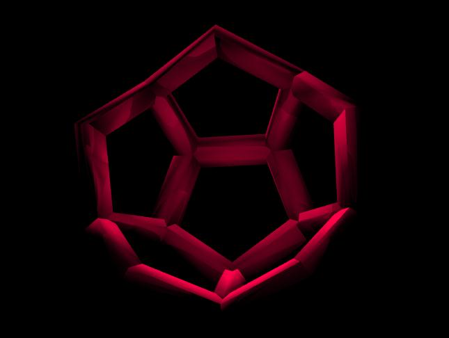
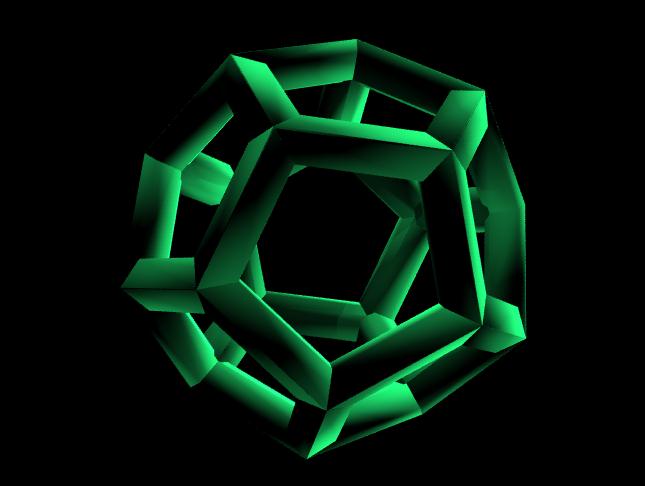
Left: The half dodecahedron rendering is perhaps more helpful that the whole when looking at the interior structure of the polyhedral. Right: My solid edge dodecahedron in all its glory. We will be printing this one out later in the week. Notice that it really does look something like a birdcage.
As you can see, Diana and I figured out how to change the color of our renderings. We also figured out how to change the background, but I really like the way the black background looks so I'm not changing it.
Wednesday June 1, 2005
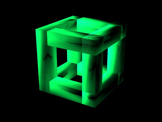
Joe decided that he would like a set of all the platonic solids in the da Vinci solid edge style. I made the cube this morning before moving on to the tetrahedron. I was playing with the translucency function when I did the rendering, so it looks somewhat textured. Here it is:
I then set to work on the tetrahedron. As the tetrahedron has only four faces it seems to be simpler than the dodecahedron. Each face is an equilateral triangle so the pieces must be beveled to fit at a 60 degree angle. However, the dihedral angle is approximately 70.53 degrees, which creates problems. The edges have thickness in three dimensions, creating problems whenever they must meet at an acute angle. I’m not quite sure what to do about this; I’ll put my mind to it tomorrow.
Joe and I also played with the extrude function today (in the hopes of getting a more perfect peanut shape) and figured out a couple of things. First of all, the extrusion really is tangent to the curve, at least when your curve is one piece. However, it seems to us that the attach function seems to do something strange to the CVs with the result that the extruded face stops being orthogonal. We've decided to try to extrude the different arcs separately and then attach the resulting sections of tube.
Thursday June 2, 2005
It might be helpful to reprint my peanut diagram, with a couple of extra points added.
I spent the morning working on the peanut shape. In the Alias help file it said that the extrude function will work best if you make the extruded face (in our case a circle) orthogonal to the path curve at the start point. Our first arc was arc BKC. I computed the slope of the tangent (to circle A) at point B and took the negative reciprocal and took its tangent inverse to find the proper angle for the extruded face. I found that the tangent slope at B was approximately -.41207 and that the angle of the profile curve should be 22.3952 degrees (Note: the tangent slope at B is not perpendicular to the segment AD). I think this is correct, because when I used the extude function the profile curve did begin orthogonal to the path curve (to my eye). However, it still the curve still did not remain orthogonal and we're still not sure how to fix this problem.
In the afternoon I continued work on the tetrahedron. I still haven't gotten a shape that is smooth on the outside, though I have managed to get it so that the vertices are smooth.
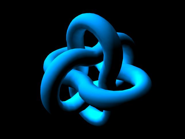
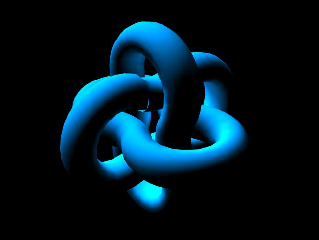
Friday June 3, 2005
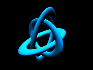
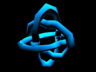
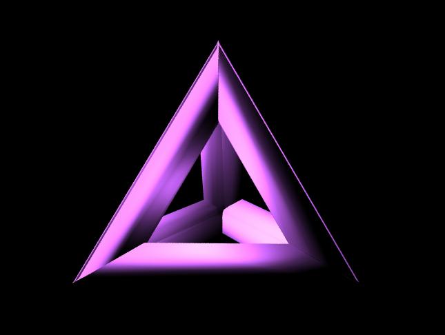
We did another print run today. This week's print included a trefoil knot and a protein backbone (both printed from files from the internet), two of Diana's joint designs, and several sizes of my dodecahedron. We spent part of the morning cleaning up and then Diana and I went over to the Engineering building with Faith, Ana, and Nell so Joe could show us the basics of POV-ray. We had a picnic lunch out on Burton lawn. In the afternoon I went back to working on my tetrahedron. I still want to take some time to perfect the fit of the different faces (I construct the edges of one open face and then duplicate them and fit them together), but I did finally get a smooth model. Here is my rough draft, as it were:
Friday's print run had finished just as we were leaving for the day, so we didn't excavate our new models until today. Samri and I spent quite a while taking all of the new models out. After we had removed all of them she set about sifting the rest of the powder (and moving it from the build bin back to the feed bin) while I used the depowdering station to clean off the models. The dodecahedrons came out very nicely, but I was a bit disappointed with the trefoil knot-- it was slightly too connected for my taste. Samri and I managed to break our protein backbone when using Z-bond (super glue) to strengthen the structure. We'll be printing out another copy on the next run, and this time we'll bond it in a safer way. We also spent some time cleaning up the room, and all of us had to update our web journals too.
Tuesday June 7, 2005
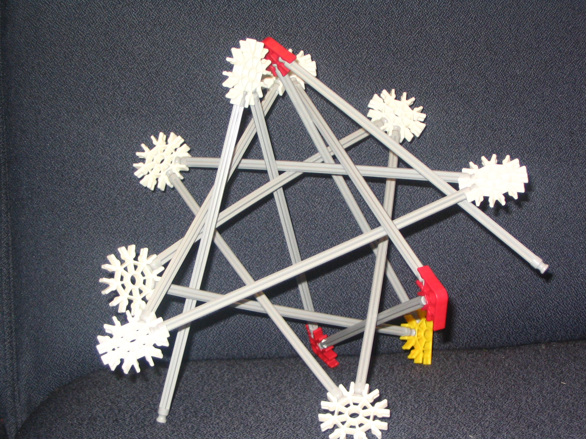
I spent most of this morning putting the finishing touches on my tetrahedron. I'm not sure how it will come out (Alias has drawn so many lines around the edges that I can't tell how clean they are), but I'm hoping it will be as nice as my dodecahedron. In the afternoon Samri and I spent some time working on a model demonstrating that an open two-chain can interlock with an eleven chain. We discovered an inconsistency in the diagram and Joe wrote to his coauthors to figure out exactly how is should be corrected. We also discovered how to use a pencil sharpener in place of a lathe-- the machine shop is temporarily on the fourth floor (due to construction) and we don't have access to most of the machines. We did manage to use the pencil sharpener to shape the ends of our dowels, making it possible to construct a three-four tangle. I also started work on the icosahedron.
Wednesday June 8, 2005
I spent most of the morning getting frustrated with my icosahedron. I have the dihedral angle, but there are so many faces that the rotations get really complex. In the afternoon we headed off to the hardware store in search of dowels and screw eyes. I didn't know exactly where we were going, so I decided to follow Diana and Samri. Big mistake. We must have gone at least a mile out of our way. Forty-five minutes later we found ourselves on King St. (finally), several blocks beyond where we meant to be. It must have been 90 degrees out there and quite humid-- not a fun experience. Eventually, however, we got what we needed to get and came back here and got back to work on our models.
Thursday June 9, 2005
Once again I spent the day getting frustrated and getting nowhere with my icosahedron, though I took breaks to work on the dowel model with Samri.
Friday June 10, 2005
I've realized that the rotations involved in creating the icosahedron are complex and that the shape needs to be broken down into parts. I've been trying to just start with one triangle and go out from there, but by the time you get more than a couple triangles away you're in a totally different plane (and it's difficult to calculate the angle between the planes when all you know is the dihedral angle... each plane meets the next one at a 138.189 degree angle but that doesn't help you in terms of rotations in x, y, an z). Joe showed me that I can break down the shape into two pentagonal caps (where the vertices of five triangles meet) and then a set of ten teeth (five pointing upward and five pointing downward) that connect them. I've started working on constructing a pentagonal cap, but so far I'm having trouble figuring out how much to rotate the triangle around the x-axis to make the pentagonal base (of the cap) coplanar.
I spent most of the day working on my icosahedron. I have successfully created the pentagonal cap which makes up a quarter of the polyhedron. I am now experimenting with ways to use it to sew the shape together. First I tried adding teeth but I found it difficult to compute the proper angle (this was compounded by the fact that I'd managed to change my shapes so that a rotation of (0, 0, 0) degrees around the x-, y-, and z-axis was strangely skewed). I then tried attaching two pentagonal caps (since on the finished shape any set of five triangles whose vertices meet at a point could be considered a pentagonal cap) and filling in the triangles on the sides to make a larger portion of the shell. This was also a failure and I'm planning on going back to my experiments with teeth.
Tuesday June 14, 2005
I've gone back to adding teeth to the pentagonal cap and I've figured out a way to make the rotations less wacky... grouping! My favorite function on Illustrator also exists on Alias! It seems to be going fairly well, but when faced with the acid test-- duplicating one half icosahedron and rotating the newly created half and fitting them together-- I can't make it fit exactly. I'm guessing there's a small error somewhere that's messing it up. I also spent part of today working on the wooden model of an 11-chain interlocked with a 2-chain with Samri. She changed the length of one section and now it is locked without being rigid. We've started painting the dowels. We're running the printer tomorrow so we spent some time preparing it. We're not sure that we've got enough powder to finish the job... I'm not sure how that's going to work out.
Wednesday June 15, 2005
We spent quite a bit of the morning setting up and starting our print run. Then I went back to working on my icosahedron. Joe and I decided that the best way to fix the little errors is to start over from the pentagonal cap. It's going faster this time, but it's still not fast. Hopefully I'll finish it tomorrow. We ran into some problems with the print run-- we ran out of powder. The machine kept going without the powder with the result that it looks like my cube has been cut off melted into goop at one end and my tetrahedron is cleanly cut off-- at a funny angle (as we were printing it at an angle). Both are very nice from the standpoint of modern art, but as models they are totally useless.
Thursday June 16, 2005
We spent this morning unearthing the remaining models. The sphere model of the protein broke (from the pressure of its own weight) when I was depowdering it. We've used this powder quite a few times, and from looking at the edges of my partial polyhedrons (both of which I also depowdered this morning), the quality of the models is really going down. Joe thinks that the sphere model (of the protein) would not have broken as it did had we used new powder.
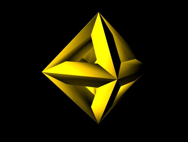
This afternoon I returned (once again) to my icosahedron. I'm happy to say that it finally worked. I now have a beautiful icosahedron ready for printing (well, I still have to convert it to an stl file). I spent the remainder of the afternoon working on renderings. Some of them are quite spiffy. However, simplest first:
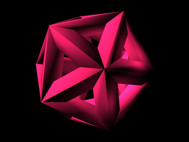
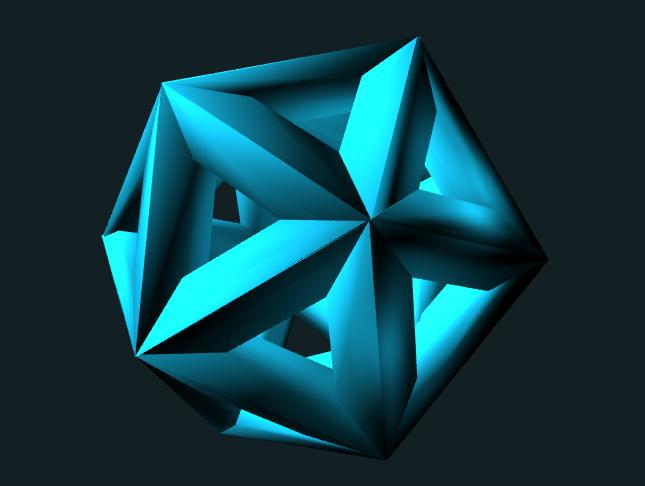
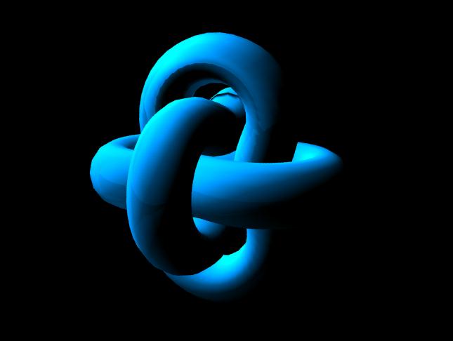
Left: a fairly basic rendering; all I did for this one was switch the color to ruby red. Right: I tried a gray background and also experimented with translucence. I made this icosahedron slightly translucent in the hopes that it might make it easier to see more of the shape. While you can't see through the shape, I think it is easier to see the different parts in this model. Note that it is rotated slightly differently (though not too much because I already had the lights placed and I didn't want to fiddle with them too much.
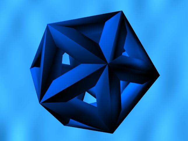
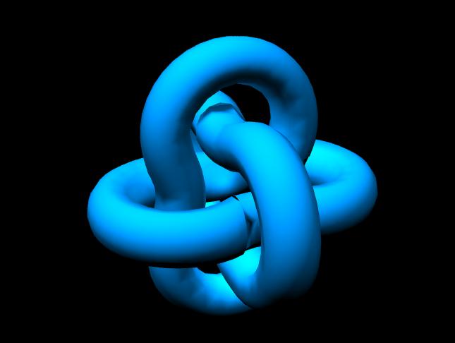
For this rendering I used the water background. I managed to get such electric blue water by tinting both the colors used-- the defaults are light and dark gray (which doesn't do a great job defining the shape unless it is a very pale color).
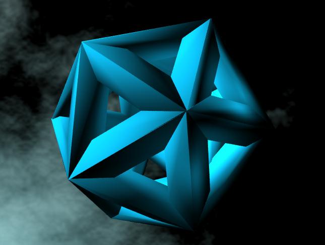
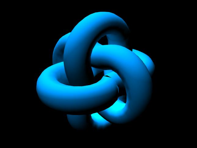
This one is definitely my favorite of all the renderings I've done. The blue of the icosahedron is light enough to contrast against the black but dark enough to contrast against the cloud (note that it's the placement of the lights that makes this work). I used the night sky background. The cloud is tinted slightly blue green so that it looks like it's reflecting the light of the icosahedron. The default color for the cloud is white. Did I have too much fun with this? Probably.
Friday June 17, 2005
I spent the afternoon working on updating this web journal (as I hadn't added to it in ages). Since it was the last time we'd all be together we decided to take a group picture. Many thanks to Kitu for taking the picture!
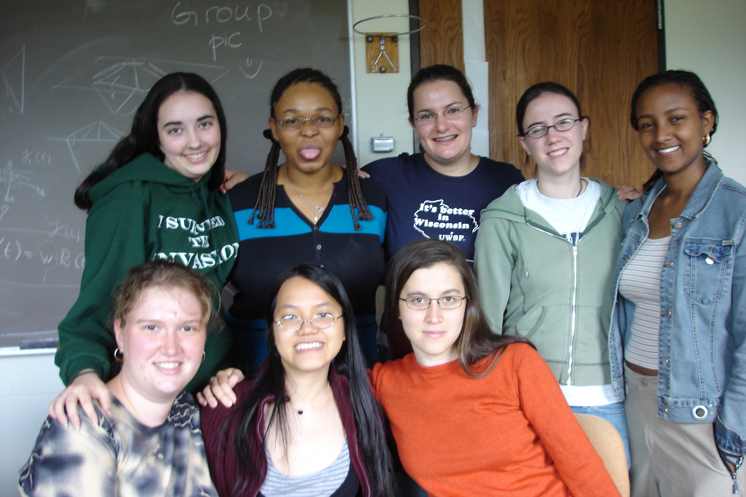
Left to Right: Top: Gillian, Diana, Faith, Nell, Samri; Bottom: Ana, Duc, Stephanie.
Yes, Diana is sticking her tongue out. She does that sort of thing.
I spent this morning and part of this afternoon updating this journal. It took so long because we had to go back and figure out what day we had done what. Luckily we had the agendas to double check. I spent the rest of the day working on the octahedron (last of the Platonic Solids). It was harder than I had thought it would be-- the beams came through each other at the vertices, creating problems similar to those I experienced when building the tetrahedron. I was much quicker this time at finding the proper angles to cut at, so it didn't slow me down too much. I managed to finish the octahedron by the end of the day, but I didn't have time to do any renderings of it yet. I'll do those tomorrow.
Tuesday June 21, 2005
I spent part of the morning making a rendering of the octahedron. I just did one simple rendering, but since the most time consuming part is placing the lights (which of course I still had to do) it took me a while anyway. Here's the final Platonic Solid:
Joe wants the edges on the octahedron, tetrahedron, and icoasahedron to be thinner for our construction of the Kepler punch bowl. These shapes are naturally less open than the cube or dodecahedron because they are constructed out of triangles (so naturally the ratio of surface area to edge is smaller for these shapes). Our original idea was to take a triangular prism shaped drill piece and "punch through" the shapes to enlarge the holes. Unfortunately, the polyhedrals must necessarily be in mesh form (because they are so complicated) and now there's no way to go back and use the cutting tool because it only works in NURBs form. We're trying to figure out another way to do it without starting over, but it's seeming like we might have to.
Wednesday June 22, 2005
Joe has an idea that we should mathematically construct each beam on Alias (instead of each face) by creating an isosceles triangle (using the dihedral angle as the controlling angle) and extrude it along a straight line, then cutting exactly so that the beams fit together at each vertex. We decided to start with the tetrahedron (since we need a thinner model for the Kepler Punch Bowl). We found that the extrusion function was not accurate. Alias showed a wire frame that was an exact extrusion, but when we filled the shape in we got a strangely stilted triangular prism-- it was as if two of the sides had been sawed at strange angles. Not wanting to give up, I tried using the cutting function on construct the beams. However, I found to my dismay that Alias would not (for some inexplicable reason) cut where I told it to cut. I could literally rotate on the perspective view and see that the cut edge did not line up at all with the shape I was cutting with. Since precision is so important, I couldn't just use what I had. I'm afraid that today I didn't find anything but dead ends.
Thursday June 23, 2005
Since Alias has proved so finicky, Joe has decided that we ought to construct the tetrahedron using Mathematica. He defined the vertices and used barycentric chords to compute the join points. My task was to define all the faces of the tetrahedron (including those on the inside). All the faces together make a solid object which we can then export and print. I finished creating the faces this morning, but when we exported it to stl and opened it in the printing program we found that half the normals were inverted. In the afternoon I spent a long time trying to figure out how to know which norms were wrong until Joe came and did a neat little trick (making the faces be different colors-- green if the normals faced outwards and red if the normals faced inwards) and explained the right hand rule (which means that the points have to be listed going in a counterclockwise direction). An hour or so later I had corrected all the normals and we exported again to stl. Then Diana and I set up the printer and began a print run (letting it finish overnight). This run included my cube, icosahedron, octahedron, and both versions of the tetrahedron (the one from Alias that I did a couple weeks ago and the one I finished today) in different sizes.
Friday June 24, 2005
This morning we went to a speech by Rita Colwell (former director of NSF and creator of the grant funding this research) at the AWIS Conference here at Smith. She was a great speaker and her speech was both fascinating and inspiring. As a result, morning meeting was slightly later than usual. The print run yesterday was large bordering on huge, so we spent almost all of the day taking care of printer related business. Diana excavated the models while I depowdered them. We also Z-bonded the smaller and more fragile models and even painted a few. Then there was the clean up-- lots of vacuuming and such. As it was Friday we also decided to tidy up the room; it's surprising how much mess can accumulate in the space of a week.
I spent today taking model photos and working on my Women in Science page, which will be a one page summary of my research this summer. Diana brought in her digital camera to take pictures of our models for the web page. So now I have pictures to go along with the renderings! I'm including a couple of them:
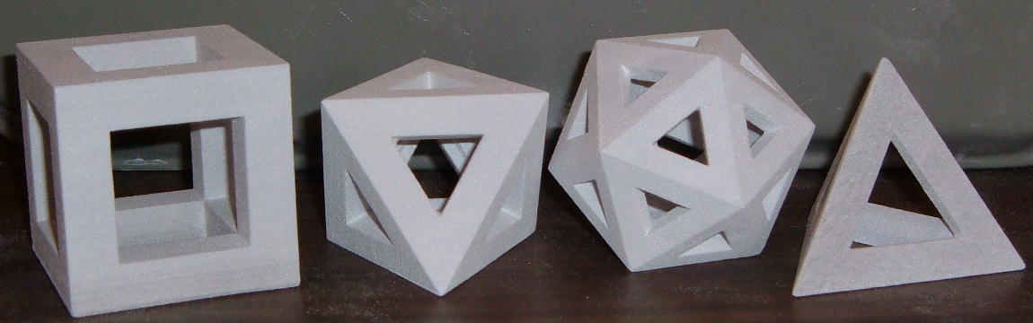
Models from our most recent print run. Unlike all previous models, they are grey instead of pink. From left to right: cube, octahedron, icosahedron, and tetrahedron. All were created using Alias Studio 12.
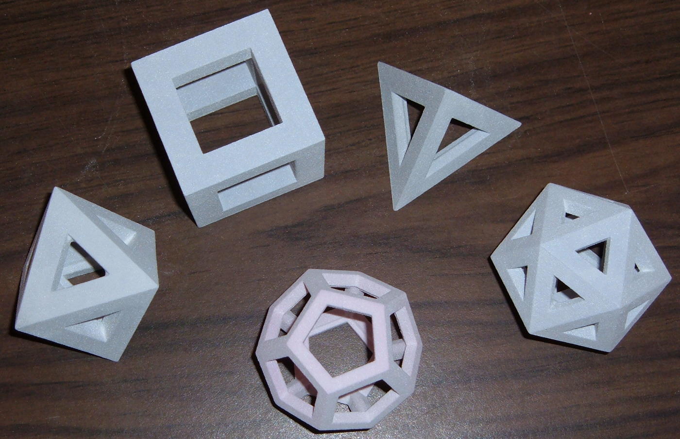
The set of all five Platonic solids as created using Alias. From left to right: octahedron, cube, dodecahedron, tetrahedron, icosahedron. All of these are unfinished models.
Tuesday June 28, 2005
Today we finished creating the octahedron with Mathematica and Joe has also started work on the programming for the icosahedron. Once again it was my job to correct the normals. We've come up with a more systematic way-- Joe has done the programming so that each edge is internally consistent, so I only have to check each edge and each cap (the piece on the inside of each vertex) to make sure the normals face the right way. I completed the first draft of my Women in Science page (the biggest difficulty was getting everything to fit on one page. It was so hard to decide what to cut!), but I'm having trouble making the images print out. I'll tackle that tomorrow.
Wednesday June 29, 2005
This morning I worked with Joe to finish both the icosahedron and dodecahedron models in Mathematica (again I had to check and fix all the normals). I also spent some time fixing up the images so that they would print out properly on my Women in Science page and making the corrections Joe had given me on my rough draft. I sent the new thinner Platonic solids (i.e. the ones we designed in Mathematica) so she could use them in a new model of Kepler's punch bowl. By the end of the day she had finished with it and so we packed the final print run. We started it just before leaving so that it will be finished when we come in tomorrow morning, leaving us plenty of time for depowdering and clean up!
Thursday June 30, 2005
We depowdered this morning only to find that most of the Mathematica shapes (all except the tetrahedron) had come out in pieces! Each edge was a separate piece. I felt like I was excavating pot shards. Late in the morning we figured out the problem. The tetrahedron was the one shape we created before Joe automated the building process on Mathematica. Like the other shapes, it has caps on the inside of each vertex. However, it does not have sets of triangles on the inside connecting the edges of each cap to the vertex of the polyhedron. These internal triangular faces made each edge into a closed beam, breaking apart the polyhedra. Joe went into Mathematica and removed the internal trirangular faces. We did a very quick (one hour) print run just before lunch to determine that this did indeed fix the problem. It did. Before we left for the day we started a redo of the print run from the day before, this time with our polyhedra connected.
Friday July 1, 2005
We unearthed the print run this morning. We've discovered that this method of constucting polyhedra (single beam edges instead of the double beam edges I used when I created the shapes on Alias) is far to fragile to use for physical models, even when they are a couple of inches tall. It works fine for the tetrahedron because the dihedral angle is fairly small, resulting in relatively thick beams. The dodecahedron has a larger dihedral angle and therefore thinner beams, making it much more fragile. Somehow Diana and I managed to get it out without breaking it. I then took it to the depowdering station and cleaned it off very carefully (and shooting the air from very far away). My depowdering skills have certainly improved since the beginning of the summer. I managed to depowder the dodecahedron without breaking any of it. Next I treated it with Z-bond (which just about doubled the weight of the model, to give you some idea of how fragile it is). Now that it is strengthened with super glue the dodecahedron is not quite as breakable, but it's still quite fragile.
Today is our last day working together on these projects. It's been a lot of fun!